
Receive Drawings, Samples, and Requirements
Understand the part application, production volume, expected quality, and technical constraints.
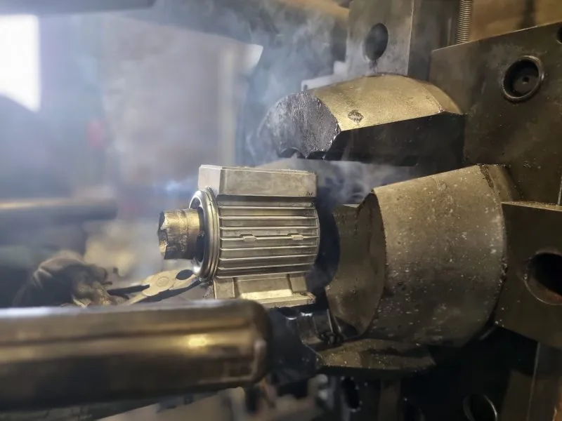
In a die-cast part, product geometry cannot be separated from the die and the process. Part design, parting lines, runner system, overflows, venting, and melt behavior are evaluated together from the outset, so engineering decisions are coherent and practical before manufacturing begins.
This stage is not simply about drawing a part or a die. The drawing, sample, production volume, and functional requirements are reviewed while the effects of geometric decisions on filling, ejection, machining, and production stability are assessed at the same time.
The process advances through continuous collaboration with the customer. Requirements, constraints, and technical proposals are reviewed in on-site or online meetings, and engineering decisions are progressively refined and finalized through discussion and feedback between the teams.
Product design and die considerations therefore move through an iterative engineering loop; each review may refine the part geometry, the arrangement of die components, or the process route.
This is not a linear, one-way process; analysis and simulation results may lead back to refine earlier stages.
Understand the part application, production volume, expected quality, and technical constraints.
Evaluate the production method, alloy, initial geometry, and post-casting operations.
Optimize wall thicknesses, draft angles, fillets, section transitions, and critical areas.
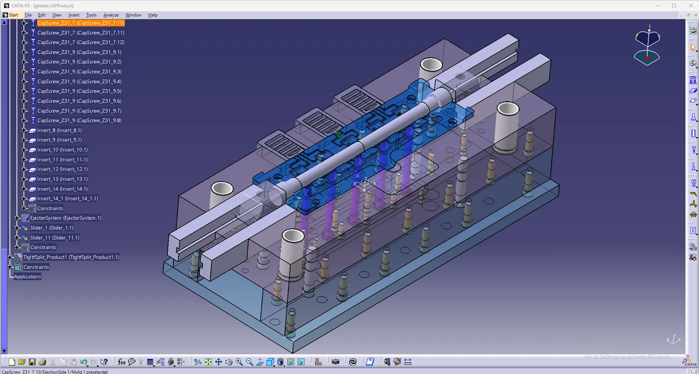
Define parting lines, runners and ingates, vents and overflows, slides, and ejectors.
Assess the filling process and feed the findings back into the design to refine decisions.
Finalize the model and documentation required for controlled release into die manufacturing.
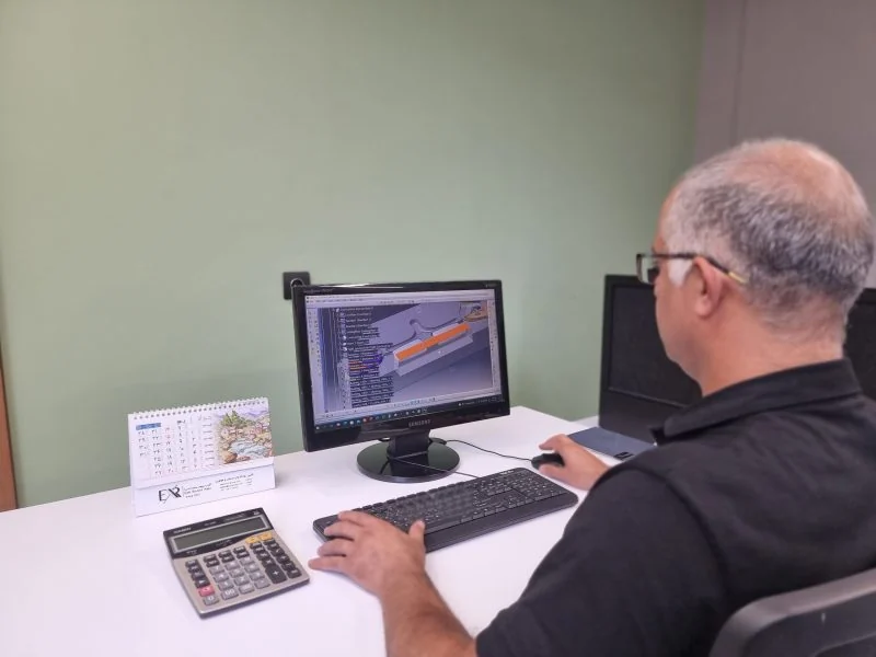
Create or revise the 3D model from a drawing, sample, or initial data while considering part function and manufacturability together.
Review geometry for manufacturability to reduce identifiable risks before the die is built.
Complete 3D design of the components that determine filling quality, part release, and die operation.
Use computational analysis to visualize process behavior and support engineering decisions—not to replace experience and physical trials.
Part Design, Assembly Design, Generative Shape Design, and Digitized Shape Editor
Core & Cavity Design and Mold Tooling Design
Advanced Machining and toolpath simulation
Computational analysis with OpenFOAM and result visualization and review in ParaView
Web-based project management from design through manufacturing, trials, and activity tracking
To begin, we review the initial project information to determine the appropriate technical route and any additional data required.